Introduction
Metal foam is a cellular structure consisting of a solid metal as matrix and voids which are interconnected resulting in lighter weight and porous structure. Metal foam can be used as a lightweight structural material in aerospace, automotive, and construction industries. It provides high strength to weight ratio and high impact resistance making it useful in crash-worthy components, armor panels, and load-bearing structures.
Aluminium foam is such metal foam which has numerous applications in different engineering fields. Aluminium foams are intentionally fabricated with high degree of porosity, and have a good combination of physical and mechanical properties 1. In particular, their good impact energy absorption capacity is the focus of interest 2.
There are different manufacturing techniques to produce metal foam. One of them is through liquid metallurgy route 3. Mainly two types of foams can be formed, one is open cell and other is closed cell. Porosity is an important characteristic of metal foams. This porosity level can go up to 95%. Density of metal foams are lower than its bulk material. It is known that with increase in density of metal foam the strength increases, this is due to fact that as density is increased material gets closer to bulk condition. Metal Foams are used in buildings due to its light weight and high specific strength. A light weight construction requires high stiffness-to-mass ratio which is found in metallic foams. 4. Structure with foam are preferable for many reasons like these are easier to manufacture with a given complicated geometry 5. Foam based structures are more robust and tolerant to damage, and the failure behavior is no more catastrophic 6. Metal foams also possess heat resistance and acoustic properties 7.
Light and stiff structures are possible to manufacture using aluminium foams. This helps to reduce the weight in components such as car, trucks, buses, etc.
There are numerous uses of metal foams in the modern industries of the world. It is known that the high stiffness and strength per unit weight make sandwich type panels suitable for modern aircrafts and aerospace vehicles, boats and high rise buildings 8. In foam based sandwich panel, additionally a core foam core is placed between two thin plates which make them strong and flexible 9-10. Another simple panel can be understood as if only foam is used to support the load and there is no any extra support in it. Buckling and bending in sandwich panel is highly restricted due to the separation between foam. A large number of core materials with such configurations are available. One is of honeycomb type in which the voids are in honeycomb shape and others are normal foams which has irregular shape of voids. The foam cores are very preferably used in areas of protection of water spillage, sound and heat insulation. Additionally, foam cores are the least expensive material among core materials and can offer many advantages during manufacturing of the foams. However, small adhesive area is the weakest of honeycomb cells with face sheets 11,12. Sometimes, due to manufacturing defects or in-service sever conditions and high mechanical loading can induce de-bonding or breakage between them. To avoid breakage filling of cores with suitable materials can be done so that it enhances the bonding resistance as higher surface area is available to take load and allows formation of new sandwich type cores. This concept combines the mutual benefits of the honeycomb and foam cores. The filling also leads to changes of the improved dynamic properties of the honeycomb sandwiches. The aim of this study is to explore the effect of the foam-filled sandwich type panels. Here, four types of sandwich panels were prepared. After this each panels were tested under load to check the deflection. The deflection was also calculated theoretically and the relation will be setup.
Foam based sandwich panel have strength to weight ratio higher. It stores more energy than other panels. These types of beams have low weight so there is no bending stress produce due to self- weight. Mondal D P, Das S et al 13 studied the compressive deformation behaviour of closed cell aluminium fly ash composite foam of varying relative densities (0.08 to 0.13) at different strain rate (10-2 to 101 s-1). The plateau stress followed the power law relationship with respect to relative density, whereas densification strain is found to be almost invariant to the relative density and the strain rate. The application of cellular materials in panels are because of light weight and good compressive strength and energy absorption 14. The analysis of sandwich plates with hollow and foam-filled honeycomb cores have also been carried out using the commercially available finite element code and numeric analysis 15-19. Corrosion resistance is better in aluminium foam because of presence of aluminium as compared to steel (COR-ten) 20. Ultimate aim of this paper is to establish the correlation between the theoretical and practical deflection in the Al-2014 foam. Different thickness of plates (0.2 mm to 1.2 mm) and core (2 mm to 12 mm) have been taken for the study. Single, double, triple and quadruple sandwich panels have been prepared and studied.
Materials and Methods
Al 2014 alloy was used for making foam using CaH2 as foaming agent and fly ash as thickening agent. The chemical composition of AA2014 (ASTM B209) used was the matrix alloy (AA2014 Al-alloy) contains 4.6 wt% Cu, 1.9 wt% Mg, 0.5wt% Mn, 0.4wt% Si, 0.5wt% Fe, 0.1wt% Ti, 0.1 wt% Cr balance Al. The particle size of fly ash particles varied in the size range of 2-10μm and it was of about 5%. CaH₂ was of 1.00 % by weight with particle size range 20-50µm. The size distribution of foaming agent CaH2 and fly ash particles are shown in Figure 1. The foams were prepared by melting it in laboratory furnace at 670oC.
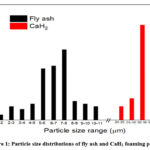 |
Figure 1: Particle size distributions of fly ash and CaH2 foaming particles. |
Multilayer sandwich panels were made using the face plate of Al-2014 and core of Al-2014 foam which was prepared using method stated above. For a single layer panel, two face plates were used and one core was used. For double layer, three face plates and two cores were used similarly one face plate and one core was increased in triple layer and further one face plate and one core was increased to make quadruple layer. The deflection was checked with 1000 N using UTM. The deflection test setup is shown in Figure 2.
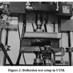 |
Figure 2: Deflection test setup in UTM. |
The preparation and deflection tests were done in following step:
Step 1: Molten foam produced in furnace were inserted between two aluminum strips and left it to cool down to form single layer sandwich panel. Similarly, for double layer molten foam was poured between three aluminum strips and left it to cool and the same process repeated to form triple and quadruple layer sandwich panel.
Step 2: All prepared samples were bend tested at 1000N to check their deflection.
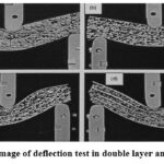 |
Figure 3: Optical image of deflection test in double layer and quadruple layer. |
To analyse the change in flexural rigidity and shear rigidity with increase in layer the calculations were done using standard formula as stated afterward.
Case I: Single layer sandwich beam:
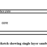 |
Figure 4: Sketch showing single layer sandwich beam. |
Flexural rigidities for single layer sandwich beam:

where,
Ec1 = Ec
c1 = c
d1 = d
The variable and constants defined in the formula are stated below:
b = width of the sandwich beam in mm
t = face plate thickness in mm
c = core thickness in mm
d = distance between the facing centroids in mm
Ef = modulus of facings=7000 MPa
Ec = modulus of core=300 MPa
Gc = shear modulus of core=200 MPa
Shear rigidity for single layer sandwich beam:

Where,
Gc1 = Gc
d1 = d
c1 = c
Case II: Double layer sandwich beam:
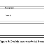 |
Figure 5: Double layer sandwich beam. |
Flexural rigidities for double layer sandwich beam:

where,

c2 = (2c + t)
d2 = (2t + 2c)
Shear rigidity for double layer sandwich beam:

where,

d2 = (2t + 2c)
c2 = (2c + t)
Case III: Triple layer sandwich beam:
 |
Figure 6: Triple layer sandwich beam. |
Flexural rigidities for triple layer sandwich beam:

where,

c3 = (3c + 2t)
d3 = (3t + 3c)
Shear rigidity for triple layer sandwich beam:

where,

d3 = (3t + 3c)
c3 = (3c + 2t)
Case IV: Quadrate layer sandwich beam:
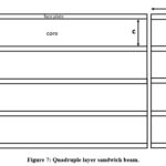 |
Figure 7: Quadruple layer sandwich beam. |
Flexural rigidities for triple layer sandwich beam:

where,

c4 = (4c + 3t)
d4 = (4t + 4c)
Shear rigidity for quadrate layer sandwich beam:

where,

d4 = (4t + 4c)
c4 = (4c + 3t)
Deflection of the single layer sandwich beam:
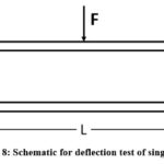 |
Figure 8: Schematic for deflection test of single layer. |

where,
F = load in N
L = distance between support span in mm
EI = flexural rigidity in MPa
AG = shear rigidity in MPa
Results and Discussions
Analysis of sandwich panel
Effect of the face plate thickness on flexural rigidity
Flexural rigidity as a function of face plate thickness for different layered sandwich panels having width, b=10 mm and individual core thickness of 2 mm is plotted in Figure 9(a). It is visible from this figure. that flexural rigidity increasing parabolically with increase in face plate thickness irrespective of number of layer in the panels. Each individual layer of face plates and foam core in between them. It is interesting to note that with the increase of face plate thickness from 0.2 mm to 1.2 mm, flexural rigidity of a single layer sandwich beam increased from 359733.3 N-mm2 to 4522400 N-mm2. This improvement is less. But, if one considers multilayer (quadruple) made with same individual layer packed one after another, the flexural rigidity increased from 9489533 N-mm2 to 99963200 N-mm2. This increase in around 10.53 times. For quadruple layer the weight increased by 5 times compared to single layer. But the rigidity increased by 26.37 times for face plate thickness 0.2 mm. Thus for designing of sandwich panels capable to withstand high force and obtain energy one must go for multilayered sandwich panels. Figure 9(a) also demonstrates that even the flexural rigidity with 1.2 mm face plate thickness is not achievable with single layer or double layered sandwich panels having core thickness 2 mm and any face plate thickness. This again signifies the importance of multilayered foam core sandwich panel.
Similar plots for core thickness of 4mm, 6mm, 8mm, 10mm and 12mm are shown in Figure 9(b-f) respectively. It is in general, noted that flexural rigidity increases with increases in face plate thickness for constant core thickness. The variation of flexural rigidity is noted to be parabolic in nature. It also noted that the flexural rigidity increases with increasing in core thickness also. The effective improvement in flexural rigidity with face plate thickness for different multilayer sandwich panels can be examined more clearly from the graph plotted in Fig 9.
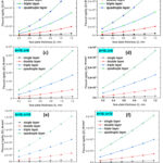 |
Figure 9: Flexural rigidity v/s face plate thickness for different core thickness at a particular width. |
Effect of core thickness on flexural rigidity
It is already being examined that the flexural rigidity of panel increases with increase in core thickness. In order to examine the trend of validation of flexural rigidity with core thickness, the values of flexural rigidity as a different core thickness have been plotted on Figure 10. Figure represents variation of flexural rigidity with core thickness for sandwich panels of different layered for face plate thickness of 0.2mm, 0.4mm, 0.6mm, 0.8mm, 1mm and 1.2mm. It is evident from this Figure that flexural rigidity increases parabolically with increase in core thickness irrespective of number of layer in the panels. Each individual layer of face plates and foam core in between them. It is interesting to note that with the increase of core thickness from 2mm to 12mm, flexural rigidity of a single layer sandwich beam increased from 359733.3 N-mm2 to 14739733N-mm2. This improvement is 40.97 times. But, if one considers multilayer (quadruple layer) made with same individual layer packed one after another, the flexural rigidity increased from 9489533N-mm2 to 533000000N-mm2.This increment is around 56.16 times. For quadruple layer the weight increased by 4 times. But the rigidity improved by 69.16 times. Thus, for designing of sandwich panels which are capable of withstanding high force and bending energy; one must go for multilayered sandwich panels Figure 10(a) also demonstrate that even the flexural rigidity with 12mm core thickness is not achievable with single layer or double layered sandwich panels having face plate thickness of 0.2 mm.
Similar plots for face plate thickness of 0.4mm, 0.6mm, 0.8mm, 1mm and 1.2mm are shown in Figure 10(b-f). It is, in general, noted that flexural rigidity increases with increases in core thickness for constant face plate thickness. The variation of flexural rigidity is noted to be parabolic in nature. It also noted that the flexural rigidity increases with increasing in face plate thickness also as shown in Fig 9.
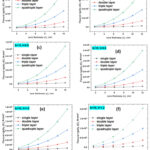 |
Figure 10: Flexural rigidity v/s core thickness for a particular width at different face plate thickness. |
Effect of beam width on flexural rigidity
In the Fig 11 which explains the flexural rigidity variation with the beam width for particular face plate and core thickness shows that the flexural rigidity increases linearly with beam width. The flexural rigidity of the single layer sandwich beam increases from 359733.3 N-mm2 to 2158400 N-mm2 with beam width from 10mm to50mm. This improvement is 6 times. But, if one considers multilayer made with same individual layer packed one after another, the flexural rigidity increased from 9489533N-mm2 to 56937200N-mm2, this increment is around 6 times. For quadruple layer the weight increased by 4 times. But the rigidity improved by 26.37 times.
Similar plots for core thickness of 4mm and 6mm are shown in Figure 11(b-f). It is, in general, noted that flexural rigidity increases with increases in beam width for constant core thickness. The variation of flexural rigidity is noted to be linearly in nature. It also noted that the flexural rigidity increases with increasing in core thickness also.
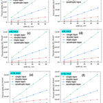 |
Figure 11: Flexural rigidity v/s width for particular core thickness at different core thickness. |
Shear rigidity
Shear rigidity as a function of face plate thickness for different layered sandwich panels having width 10mm and individual core thickness of 2mm is plotted in Figure 12. It is evident from this figure that flexural rigidity increasing parabolically with increase in face plate thickness irrespective of number of layer in the panels. Each individual layer of face plates and foam core in between them. It is interesting to note that with the increase of face plate thickness from 0.2mm to 1.2mm, shear rigidity of a single layer sandwich beam increased from 4840 N-mm2 to 10240N-mm2. This improvement is less. But, if one considers multilayer (quadruple layer) made with same individual layer packed one after another, the flexural rigidity increased from 7580659.816N-mm2 to 71205136.74N-mm2. This increment is around 9.39 times for quadruple layer the weight increased by 4times. But the shear rigidity improved by 90.32 times Thus, for designing of sandwich panels capable to withstand high force and obtain energy one must go for multi-layered sandwich panels also demonstrate that even the flexural rigidity with 1.2mm is not achievable with single layer or double layered sandwich panels having core thickness 2mm. But any face plate thickness, this again signifies the importance of multi-layered foam core sandwich panel.
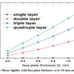 |
Figure 12: Shear rigidity with face plate thickness at b=10 mm and c= 2mm. |
Deflection of beam
When flexural rigidity increased then deflection of the sandwich beam decreased. If sandwich beam has more flexural rigidity than this sandwich beam sustains more bending moment because as bending moment is directly proportional to flexural rigidity.
When shear rigidity is increased then deflection of the sandwich beam decreased. It is further to be noted that the deflection of beam reduced significantly due to synergic reduction in flexural rigidity and shear rigidity in a multi-layered panel. For quadruple layer the deflection is reduced by 30 times thus for rigid structure multilayer sandwich panels are preferred. Fig. 13 shows the deflection values with shear rigidity and flexural rigidity. Flexural rigidity is more responsible for providing the stiffness towards the bending.
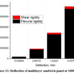 |
Figure 13: Deflection of multilayer sandwich panel at 1000 N. |
Experimental validation
Bending test on single layer sandwich beam, double layer sandwich beam, triple layer and quadruple layer sandwich beam of face plate thickness 0.2 mm; core thickness 2 mm, beam width 10 mm and beam length 60 mm have been conducted. In the experiment the deflection in the sandwich beam have been measured. The result is shown in Table 1. The values of young modulus of face plate Ef=70GPa, the young modulus of core Ec=3GPa and shear modulus of core Ge=200MPa were taken from the measured value of young’s modulus and shear modulus an Al-alloy and Al-foam. The load is kept 1000N and 1500N, the deflection of the sandwich beam is measured, the values of deflection of the sandwich beam is presented in Table 1 for single layer, double layer, triple layer and quadruple layer sandwich beam.
Now predicted deflection in the sandwich beam are compared with the deflection occurred in the sandwich beam by the experiment in the Table 1.
Table 1: Predicted and experimental values for deflection for single layer, double layer, triple layer and quadruple layer.
|
Load (N) |
Single layer |
Double layer |
Triple layer |
Quadruple layer |
||||
|
Exp. (mm) |
Predicted (mm) |
Exp. (mm) |
Predicted (mm) |
Exp. (mm) |
Predicted (mm) |
Exp. (mm) |
Predicted (mm) |
|
|
1000 |
14.966 |
15.608 |
2.362 |
2.681 |
1.416 |
1.022 |
0.559 |
0.507 |
|
1500 |
21.572 |
23.412 |
4.977 |
4.021 |
1.726 |
1.533 |
0.859 |
0.760 |
The experimental values are in good agreement with the predicted value. The improvement in these properties are in good agreement with the reported values also. Least deflection is shown in quadruple layer
Conclusion
Here we designed multilayer sandwich beam and mathematical equations are derived. According to that equations we have calculated the stiffness of different layers’ sandwich beam and found that the stiffness of the double layer sandwich beam is more than single layer sandwich beam and triple layer sandwich beam have more stiffness than double layer sandwich beam and quadruple layer sandwich beam have more stiffness than triple layer sandwich beam. The multilayer sandwich beam stores more energy. So the multilayer sandwich beam is suitable for structural applications. However, there is no theoretical limit of number of panels to be used for effective improvement. But due to practical limitation on manufacturing and complexity, study upto four layers were done.
For this reason, quadruple layer sandwich beam has higher flexural rigidity and shear rigidity Than single layer, double layer and triple layer sandwich beam. Double layer sandwich beam have higher flexural rigidity and shear rigidity than single layer sandwich beam. Triple layer sandwich beam have higher flexural rigidity and shear rigidity than double layer sandwich beam. The flexural rigidity and shear rigidity increases exponentially with face plate thickness and core thickness. The deflection increases exponentially with increase the face plate thickness and core thickness.
The flexural rigidity and shear rigidity increases exponentially with increase in number of layer. Thus deflection decreases exponentially with number of layer. Deflection measures at both loads (1000N and 1500N load) was 0.559 mm and 0.859 mm respectively for quadruple layer, which is very less. The predicted values are in good agreement with the reported values and also with experimented values. Them signifies the validity of the developed analytical model.
Acknowledgement
Authors would like to thank AMPRI Bhopal for the material and experimentation. In BHEL, Mr. Tushar Dave, AGM Metallurgy is highly appreciated for encouraging and motivating during entire work.
Conflict of Interest
Authors declare no conflict of interest.
Funding Sources
This was supported by Bharat Heavy Electricals Limited through PIR No: 2022108.
References
- Simone A. E., Gibson L. J. Aluminium foams produced by liquid state processes. Acta Mater. 1998;46(9):3109-3123 https://doi.org/10.1016/S1359-6454(98)00017-2
CrossRef - Rajak D. K., Kumaraswamidhas L. A., Das S. An energy absorption behaviour of foam filled structures. Proced. Mater. Sci. 2014;5:164-172 https://doi.org/10.1016/j.mspro.2014.07.254
CrossRef - Karuppasamy R., Barik D. Production methods of aluminium foam: A brief review. Mater. Today: Proceed. 2021;37(2):1584-1587 https://doi.org/10.1016/j.matpr.2020.07.161
CrossRef - Garai F. Modern applications of aluminium foams. Int. J. of Eng. and Manag. Sci. 2020;5(2):14-21 https://doi.org/10.21791/IJEMS.2020.2.3
CrossRef - Parveez B., Jamal N. A., Anuar H., Ahmad Y., Aabid A., Baig M. Microstructure and mechanical properties of metal foams fabricated via melt foaming and powder metallurgy technique: A Review. Materials. 2022;15:5302 https://doi.org/10.3390/ma15155302
CrossRef - Sahu S., Mondal D. P., Cho J. U., Goel M. D., Ansari M. Z. Low-velocity impact characteristics of closed cell AA2014-SiCp composite foam. Compo. Part B. 2019;160:394-401 https://doi.org/10.1016/ j.compositesb.2018.12.054
CrossRef - Lu T., Kepets M., Dowling A. P. Acoustic properties of sintered FeCrAlY foams with open cells (I): Static flow resistance. Sci. China Ser. E-Tech. Sci. 2008;51:1803-1811 https://doi.org/10.1007/s11431-008-0104-y
CrossRef - Shukla A. K., Majumdar J. D. Studies on microstructure and mechanical properties of aluminium foam prepared by spray forming route. Procedia Manuf. 2019;35:861-865 https://doi.org/10.1016/ j.promfg.2019.06.032
CrossRef - Wang X., Wang X., Jian K., Xu L., Ju A., Guan Z., Ma L. Mechanical properties of Al Foams subjected to compression by a cone-shaped indenter. ACS Omega. 2021;6(42):28150-28161 https://doi.org/10.1021/acsomega.1c04217
CrossRef - Rui D., Wang M., Wang D., Zengrong H., Green M. D., Nian, Q. Understanding mechanical behaviour of metallic foam with hollow struts using the hollow pentagonal dodecahedron model. Scripta Mater. 2020;182:114-119 https://doi.org/10.1016/j.scriptamat.2020.03.001
CrossRef - Valente G., Ghasemnejad H., Srimanosaowapak S., Watson J. W. Advancement in design and failure analysis of aluminium foam-filled honeycomb crash absorbers. Appl. Compo. Mater. 2023;30:705-706 https://doi.org/10.1007/s10443-023-10116-w
CrossRef - Song S., Xiong C., Yin J., Cui K., Sun H., Han C., Huang B. Effects of polymethacrylimide foam reinforced aluminium honeycomb sandwich under quasi-static compression. Polym. f. Advan. Techno. 2023;34(8):2482-2500 https://doi.org/10.1002/pat.6066
CrossRef - Mondal D. P., Goel M. D., Das S. Effect of strain rate and relative density on compressive deformation behaviour of closed cell aluminium-fly ash composite foam. Mater. and Des. 2009;30(4):1268-1274 https://doi.org/10.1016/j.matdes.2008.06.059
CrossRef - Berggreen C., Simonsen B. C. Non-uniform compressive strength of debonded sandwich panels –II: fracture mechanics investigation. J. of Sandwich. Struc. and Mater. 2005;7:483-517 https://doi.org/10.1177/1099636205054790
CrossRef - Burlayenko V. N., Sadowski T. Analysis of structural performance of sandwich plates with foam-filled aluimium hexagonal honeycomb core. Comput. Mater. Sci. 2009;45(3):658-662 https://doi.org/10.1016/ j.commatsci.2008.08.018
CrossRef - Tang E., Yin H., Chen C., Han Y., Feng M. Simulation of CFRP/aluminium foam sandwich structure under high velocity impact. J. of Mater. Res. and Tech. 2020;9(4):7273-7287 https://doi.org/10.1016/j.jmrt.2020.04.093
CrossRef - Djamaluddin F., Mat F., Sarah Z., Ahmad M., Renreng I. Analysis of energy absorption of aluminium foam fenders under axial loads. J. Phys.: Conf. Ser. 2021;2051:012038 https://doi.org//10.1088/1742-6596/2051/1/012038
CrossRef - Tanimoto Y., Nishiwaki T., Shiomi T., Maekawa Z. A numeric modelling for eigenvibration analysis of honeycomb sandwich panels. Composite Interfaces. 2001;8(6): 393-402 https://doi.org/10.1163/ 156855401753424433
CrossRef - Birla S., Mondal D. P., Das S., Khare A., Singh J. P. Effect of cenosphere particle size and relative density on the compressive deformation behaviour of aluminium-cenosphere hybrid foam. Mater. and Des. 2017;117:168-177 https://doi.org/10.1016/j.matdes.2016.12.078
CrossRef - Sharma V., Sharma J.K., Kumar S., Panwar S. Age hardening in COR-Ten steel. IJITEE. 2019;9(2):3001-3004 https://doi.org/10.35940/ ijitee.B8113.129219
CrossRef


